How to build a small self driving car?
2017 · Amsterdam
My recent side project is a building small self driving car with
my friend Filip. See the code on
my github.
There is fair amount of folks doing similar projects, there are even people who
race these things. If it looks interesting, you could do it too - it is easier than
ever and I'm sure you'd learn a lot.
* Idea *
The car works in the following way:
-
On board of the car there is forward facing RasPi camera.
-
The image stream is sent to GPU computer,
which streams steering commands back:
"go forward", "stop", "turn left", etc.
-
Steering commands are issued in one of two ways:
-
Human input, where you steer the car in racing video game fashion.
-
Self-driving algorithm, which tries to guess what would a human do
based on current video frame.
Below diagaram visualizes the flow of data:
To enable all of this, pieces of various software infrastructure and hardware
are necessary.
On the GPU server side we need:
- code
that receives images from RasPi
- code
that sends current steering state to the car
- code
that executes neural network to obtain autonomous steering
- code
that displays user the "steering game" and collects steering
- code
that collects human input pairs and saves them to the drive
Each of the above is
multiprocessing.Process and they share a state
which is
multiprocessing.Namespace.
On the RasPi side we need:
- code that receives steering commands and executes them
- code that captures video stream and puts it on the wire
On the hardware side there are the following elements:
- Raspberry Pi
- RasPi battery pack
- RasPi compatibile camera
- RC Car
- RC car engines battery pack
- Engine controller to control RC car
- Wifi interface (turns out it needs to be strong)
- Ways to keep all of this together
In the text below I will explain how we figured out
how to combine all of them into a small self driving car,
and hopefully convey that it was a lot of fun.
And that perhaps we have even learned a little.
* Before the first car *
The whole story started when I finally had time to learn some electronics.
I have always wanted to understand it, as it delivers such exceptional
amounts of value and - in my book - is as close to magic as it gets.
It is so good:
- has light-hearted vibe about it,
- teaches you the practical basics via small projects:
- how to solder,
- how to use multimeter,
- is exceptionally easy-to-read.
It lacks the proper theory build-up, so you will have to read up on that
somewhere else if you are interested, but for the car project it should be
sufficient. After some lazy evenings with soldering iron I was able to reverse
engineer and debug basic electronic circuits such as this "astable
multivibrator", to use the proper name:
* The first car era *
Armed with knowledge of rudiments of electronics, it was time to reverse
engineer how an RC car works. As I generally had little idea what I was doing,
I have decided to get cheapest one I could find so I wouldn't be too wasteful
if I broke it while disassembling it. The cheapest one I could find was this
little marvel:
which I have bought in Dutch bargain store Action.nl, new, for below 5 euro.
Deconstructing it, you just cannot help wondering how
simple and elegantly designed it is.
It truly amazes me that for under 5 Euro per unit
people are able to design, fabricate, package, ship
and sell this toy.
It is possible mostly due to amusingly "to the point", "brutalist"
design, where most of elements are right on their tolerances
and wanted effects are achieved in the simplest possible way.
This approach is best showcased by the design of the front wheels
steering system, which I will describe below.
Coming back to the self-driving project, when we pop the body
of the frame, we see this:
Luckily for our project,
this construction can be adapted to our needs in a straightforward fashion.
In the center we see the logic PCB.
There are three pairs of red & black wires attached to the PCB:
- a pair feeding power from the battery pack
- another pair sending power to the back motor, which movese car forward and backward
- one more pair sending power to the front wheel steering system
When logic board receives radio inputs, it (more-or-less) connects
the battery wires with the engine wires and the car moves.
You can see for yourself - if you directly connect the pair from the battery to
the pair coming from one of engines (front or back engine), you see that the
wheels move in wanted directions. So if we substitute the current logic board
with our custom RasPi based logic board that controls connection between
battery and engines based on instructions that we control by code, we would be
able to drive-by-code.
Warning!
As Raspberry Pi has some General Purpose Input/Output (GPIO) pins
it is tempting to try to hook up the engine directly to RasPi.
This is a very bad idea, which will destroy your RasPi, by running too much
electricity through it.
Thus, we need to implement a hardware engine controller which based
on signals from Raspi will drive the motors.
You can buy a ready motor controller or be thrifty and implement your own.
As conceptually the wanted mechanism of action sounds like transistor -
"based on small electricty turn on flow of bigger electricty" -
I have decided to build my own engine controller.
Following
this tutorial
produced an engine controller based on L293D chip.
The tutorial worked - at least partially. I was able to steer the front wheels
and move the car forward, but there was no reverse gear.
Turns out the method shown in the above tutorial couldn't spin second engine
in the reverse direction.
After consulting the
chip's factsheet
I have come up with another way of hooking up L293D, which fixed the bug.
Now I could control car completely from Python code running on RasPi.
Now, as I had a car that can be controlled by keyboard attached to RasPi, it
was time to make the control remote. I have connected a basic small WiFi dongle
to Raspberry and implemented a pair of Python scripts:
- Server-side script capturing keyboard events and sending control
events based on them to RasPi,
- RasPi-side script listening for those events on TCP socket and based on them
steering the L293D and in turn, the car.
* Steering mechanism in first car *
Now I will describe how steering is implemented mechanically
in the first RC car we have been working with.
Let me remark here that I am impressed by how simple this mechanism is.
Perhaps the reason I am so excited about it is because I have only a vague
idea about how mechanical design works, so I am easy to impress, and perhaps
stuff like this gets done every day, who knows. But I see an element of playful
master in it and I can't help feeling happy about it.
The mechanism is hidden if you look from the front
and similarily remains hidden if you look at it from the top.
It is only after removing the top cover that we see the following mechanism
(I have removed all the plastic elements to help visibility):
Seen from the top:
And here comes the trick:
On top of shaft there is a pinion. The pinion is just slid on shaft, without
any kind of glue. The size and tightness of the pinion are chosen in in a way
that when the engine starts moving, the friction between shaft and pinion is
just enough to move the half-circle rack.
But when the half-circle rack hits
the maximum extension point, the friction breaks and the shaft spins around
inside pinion. Is there a cheaper trick (speaking both symbolically and
literally)? How ingenious!
Below the semicircular rack there is a spring that pulls the wheels back
to neutral position:
You can see it better in this close-up:
A small plastic element is connected to wheels. It has a small peg
that sits in the middle of the spring, so the spring an act on it:
So as you can see just a collection of as simple as possible
elements each doing its job well. Everything is super cheap,
but the materials and their shapes are chosen in a smart
way that makes it all work together well. So cool!
That wraps up the description of the "brutalist"
steering mechanism. Back to self driving!
* Hardware coming together *
When we had already the "drive by keyboard attached to RasPi by cable"
capability, we wanted to test remote control of the car.
In order to do that, we needed to power the RPi.
Not sure about how much power it needs, we have bought a pretty big power
bank for mobile phone with electric charge of 10.000 mAh, weighting around 400 g.
I am huge fan of American automotive show
Roadkill,
in which two guys, mostly by themselves, fix extremely clapped out classic
American cars, usually on the road / in WalMart parking lot / in the junkyard.
Typically they take some rotten engine-less chassis and put in a
cheapest-they-can-find V8 into them. Needless to say, they are masters of
using zip-ties.
Inspired by Freiburger and Finnegan experiences, I have relied on ziptie engineering
in order to combine the collection of parts into one coherrent vehicle
that will move together. The end product looked like this:
You may say that it looks pretty, but that's about all it did. Notice how big
the battery is in relation to the car. Turns out, it was way too big.
Unfortunately, the car was significantly too heavy to move on its own.
So the heaviest part of the car was the battery pack powering the RasPi. After
getting some initial experiences it became clear that 10000 mAh is a lot of
more than sufficient power to run RasPi on, even with WiFi interface for
reasonable amount of time. Thus it was easiest to save weight by buying a way
lighter battery with less capactiy.
We were really lucky about the Pokemon Go craze that has rolled through the Netherlands
in early 2017, as it meant abundant supply of cheap mobile battery packs.
We quickly sourced a new one, and with the new battery, the car looked like this:
Unfortunately, the car was still way too weak to drive well with RasPi
strapped to its back. We needed a bigger car, but before I describe it,
I will show how we have put together image capture and streaming system.
* Image capture and streaming *
Building this subsystem was a big loop of trial and error.
In the end we have settled for RPi Camera on hardware side and
amazing picamera Python module.
An interesting detail here is camera holder. Filip works in
3D Hubs, an Amsterdam based 3d printing
company. As a perk, team members are given significant 3D printing allowance,
which we used to 3d print case for RasPi camera in high quality. In this
technology they shoot plastic-paticle spray with laser so it solifidies. This
technology results in very accurate and resilent products.
When it comes to the code side, at the beginning we have struggled a lot with
high latency:
and then experimented some more:
and even more:
but quickly we have converged to a pretty resilent UDP based stream. The code
version that has worked best for us in the end was version presented in
Advanced Recipes in picamera docs, but with UDP based connection. You can
see the code
here. After this, we were consistently seeing good latency:
Measuring latency takes both hands.
Here is how the final user interface looks like:
What does the self-driving car see when it sees itself in the mirror?
* Second car *
After the first car wouldn't move under it's own weight even with light battery
pack, it became clear we need a new one. In the local shopping mall, this
time in a proper toy shop we have found this car:
which is a bigger and slightly more advanced construction.
However, in this car we can find some interesting mechanical pieces
such as rear differential, and slightly more advanced front steering.
For now, I have resisted the temptation to tear it completely apart,
but I think I will come back to it after we move to bigger car.
The disassembly yielded a similar result for our project - three wire pairs,
one for battery, one for front steering one for back steering.
As we didn't want to disassemble the front steering, we were unsure
whether it will work in the simple, linear way. That is whether by just
applying voltage to front we could steer the car.
We tested it by hand:
and luckily it worked, which meant we could reuse the previous engine control
unit. We used the opportunity to clean up the control module a bit and fit it
into slightly tighter package.
Overall, the ready product looked like this:
After this we added above described high quality camera holder.
The black car turned out to be quite fast:
And it was fun to just drive it around.
* Remote control *
Of course, driving by wire didn't cut it for us.
We have decided to stream the steering over WiFi. Another
viable alternative was Bluetooth.
First we have implemented event based controller that listens for keyboard
events on the controller server side. If it catches any, it sends a message
over TCP socket to the car to update the remote state.
On the testing bench, it has worked just fine:
But in practice, it was error-prone:
The default WiFi dongle we have bought for RasPi was too small and had not so
strong reception. It was easy to get into a spot where there were problems with
instant transfer of the data. As the TCP retries sending the data until
succesful, by the time the information arrived onto the car, several new events
might have happened. The car did not feel very responsive.
We partially resolved this issue by:
- sending the state (spamming?) to the car every 10 ms
- allowing information loss by switching to UDP
so in the new implementation, algorithm listens for keyboard events and
updates the state based on it and we send the state to the car all the
time over and over again. You can see the final code
here
and
here.
These changes in code helped the reliablity a lot, but it still wasn't perfect. Still
in places with weak wifi reception, the car didn't work pefectly.
We felt there is still room for improvement.
We tried the easiest thing there was and added stronger Wifi dongle.
We went for pentesting-style Alfa wifi dongle with reasonably big antenna.
Look how well the dongle sits between the back engine and wing.
It's almost as if we planned it to be constructed that way!
But we did not. It's just a bunch of zipties.
This concluded the hardware part for now.
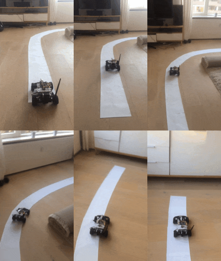
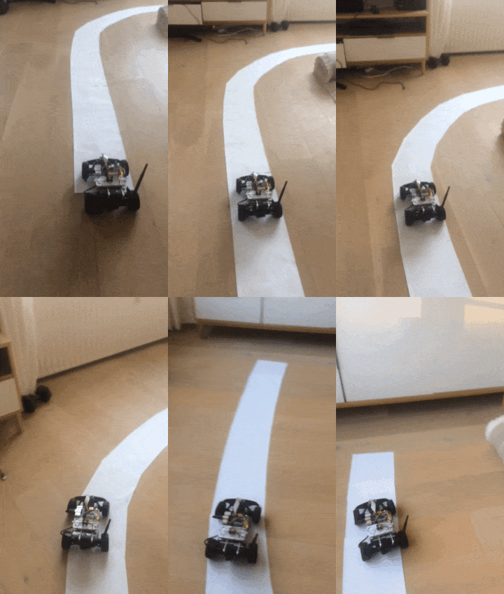
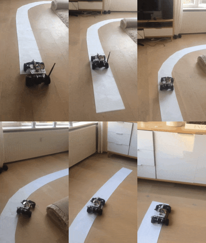
This is how it looks when you (badly) drive the car around the track in the evening.
Machine learning
We have implemented ConvNet-based behavioral cloning system that
steers the car.
It is a variation of a widely used Nvidia implementation.
See the full code
here.
The inspiration came from many places:
As shown in the diagram at the top of the blog post, based on a dataset of
pairs (image, steering) sampled from a human driving record, we
learn to predict steering from image from camera
. This is done by using a convolutional neural network.
There are good resources galore on deep learning / neural nets online, so I won't go into
detail how this was implemented. Instead, I will focus on explaining
differences between our and Nvidia's approches.
First of all, in our case the steering is binary. In a typical real-world
self-driving car implementation you would gain control over steer-by-wire
system done by car manufacturer. This usually means you gain control
over pretty precise actuators that allow you to set the steering angle with
consistency and precision. This was not the case in our model. Currently we
only have three steering states - steer full left, steer full right or no
steering. Additionally, when returning from full steer to the neutral
position, the mechanism is often not completely accurate and returns only to
somewhat-neutral position with bias to one side that is noticeable when the car
goes fast. Check the driving video linked above and compare how fast everything
happens compared to driving a normal car.
Secondly, in our implementation we only use one camera, where Nvidia's
implementation uses three cameras that are generally forward facing,
but at slightly different angles.
This trick is done to get rid of a problem specific to behavioral learning.
The problem is overrepresentation of idealized trajectories in the training data.
If you consider a person driving a car on a road, even on a closed-off private road,
the samples from the car going off-road, or near-crashing and recovering in the
last moment are extremely rare compared to calm driving in the middle of the world.
However, for the algorithm both cases are as important as the other.
The self driving systems needs to know what to do when it starts going away from middle
of the track.
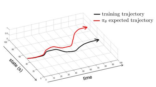
You can see in this image that during the training, we have explored the black trajectory.
Due to inherent randomness, we are slightly diverging from the most well-known
trajectory, for example the car steers a bit more to the right then usually.
The correct response would be to correct and go back to the middle of the
track, but there is no data like this in the training dataset (or there is
but it is not sufficiently frequent to be represented in the machine learning).
The solution to this is to build a distribution of cost (and therefore, of
wanted behaviours) around the optimal trajectory:
Image, again courtesy to UC Berkeley, Prof Sergey Levine.
There are several ways one could go around producing such a distribution.
One could try to gather a lot more data, especially taking care to sample
trajectories that are away from the optimal trajectory. In the case of the car it
could be turning off recording, steering slightly off the center of the road,
turning recording back on, correcting the steering back to the center. Another
idea would be to drive over the same piece of road many times, taking care to
drive a bit to the left, than a bit to the right, then more to the right etc.
As you can see, these solutions are doable, but not extremely practical, so it
is not always there is an easy way to just gather the data.
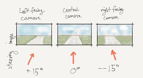
One could consider the trick that Nvidia has done. They have set up two cameras at slight
angles to left and right
in addition to the central forward facing one.
Then they correct for this in the steering commands that are recorded
as the pair for that sideways facing image.
So for example if they are driving straight forward, the right facing
camera will record a picture as if the car was going to the right of the
road, and a steering correction of the same angle to the left would be added
to the current (fully straight steering).
This will help the machine learning algorithm understand that
it needs to steer left when it sees this image.
In our case the problem is less severe than in the case of the real self-driving car.
This is because:
-
we have less general problem. The variety of tracks that we can build around the house
is significantly smaller than the variety of real roads, especially when you
take into consideration the spectrum of possible lighting conditions.
Our track is white pieces of paper, which is very clearly visible and
similar to itself under a variety of conditions.
- the tracks that we train on are shorter so we can run the car
over each piece of road hundreds of times in a day or so. Imagine doing that
for each piece of road in Europe or US.
- We have significant variations of runs due to lack of precision of our
actuators. Driving in the small car world is a lot more dynamic,
the turns are a lot sharper and we can afford to crash for free.
Check out driving video above to see how quick everything happens.
We have also added some more layers to the NVIDIA architecture, but I don't
think it should make a big difference (as the structure of the data we have
is relatively simple).
One more difference is purely architectural - NVIDIA has run the deep learning
directly on the car, using cutting edge (but super expensive)
NVIDIA DRIVE PX computer for autonomous driving.
NVIDIA claims that they got 30 fps, and we got 25 fps, so I would say not too bad.
In general the system works well on the track it was trained on, but the
performance doesn't generalize to a more complicated, tighter track. We will run
some experiments about training on the new track soon. My guess the
performance should be improving steadily with amount of training data gathered.
You can see that even on the vanilla one-turn track the driving is not perfect,
doesn't stay inside of the track, but with the current controls it may be
beyond possible. It should be possible with a car that has more precise, preferably
non-binary left-right steering.
* Machine learning development story *
From the beginning of the development, we were pretty sure that our approach
should work - we knew it has been applied sucessfully in real life applications
and very similar project but inside of simulator was part of Udacity
self-driving car course. Still, getting it right required some degree of patience
and creative tweaks.
After the hardware construction & testing phase, we had a real-time, low-latency system where you
drive the car around track, based solely on the video input.
The final user interface looks like this:
Here you can see a previous iteration of it being tested carefully by another friend.
So we started off with gathering one big track, around 10 meters around the
whole house. In this iteration, everything that we did was "on camera"
and got appended to the dataset.
We have trained a neural net same as in the Nvidia paper. It didn't work! And
by didn't work we don't mean running it once and declaring failure. In
general, we tried to make at least three optimization runs for each setting of
architecutre / metaparameters to be sure to take out effect of random
initialization.
After the initial attempt didn't work, we decided to simplify the problem to
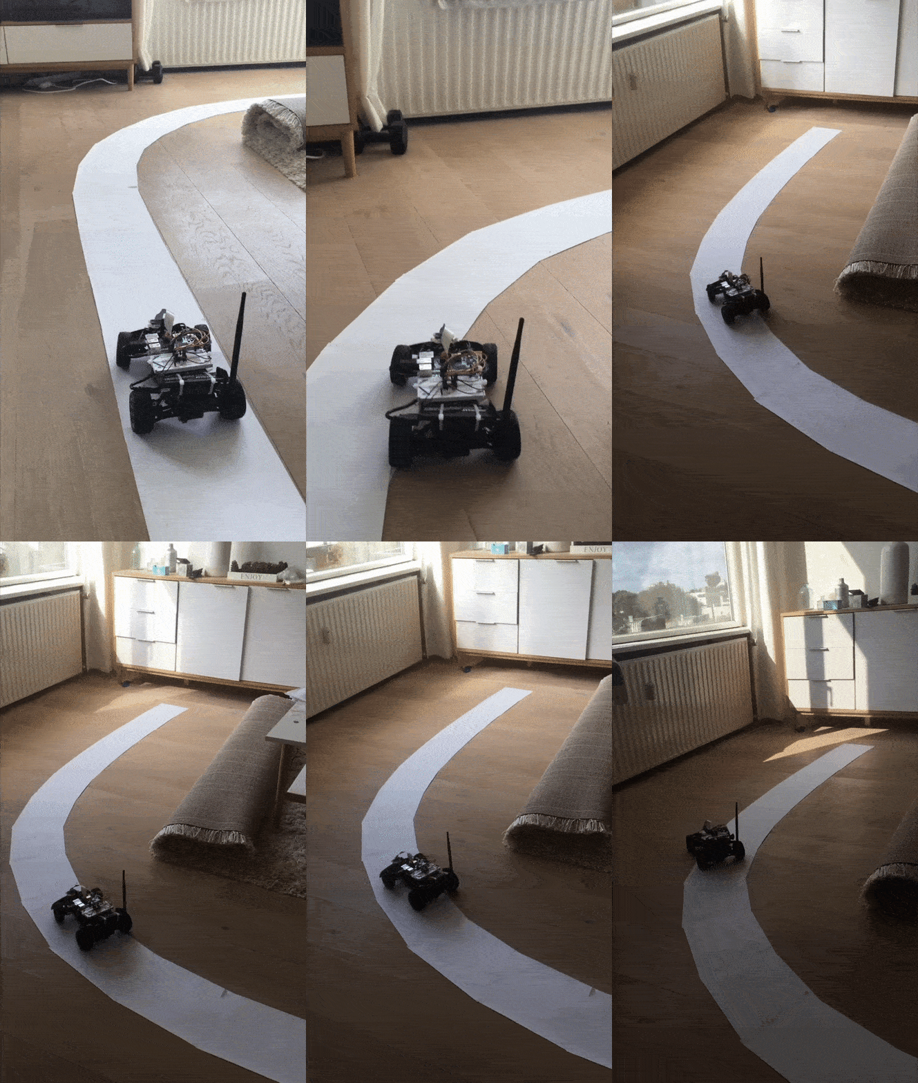
just one turn. We have gathered a lot of data another time - more or less 2
sessions of 2 hours each. The raw collected pictures look like this:
After training the network we have found that again it doesn't work. We had a
brainstorming session we decided that most effective would be to implement a
manual data adjuster. We were thinking that perhaps there was too much error
in our training data (that we were driving too much outside of the lane as
things were happening too fast, that there was overrepresentation of start of
track and end of track with 0 velocity but nonzero steering). We have
implemented some additional infrastructure to help debugging this kind of data
errors - a data viewer / editor, capability to turn recording on and off in
data collection, a dataset combiner. Then we manually went through all of the
data and corrected what we thought were inconsistencies. This also didn't
work...
Then we spent some even more time looking at the data and only then we have noticed
that horizon is located differently in different parts of the dataset.
That meant that our camera was moving around too much, introducing
significant noise in the data.
We have fixed the camera placement, added a guiding line in the driver UI and
collected more data. Still didn't work!
Then we had the breakthrough, which was noticing that we should cast to grayscale
and implement brightness and contrast adjustments. We do it to correct for
differing lighting conditions. An example of our final augmentation pipeline is
visible below:
Than it finally worked! Somewhat... The car doesn't stay perfectly inside of the track
(everything happens so much faster compared to real life car)
We only tested the whole project well only around one turn track.
We can squeeze out / cheat a run that doesn't exit track
around a more curvy, tighter track, but it doesn't count. But still
it shows some degree of generalization.
We think that if you just gather more data with the current architecture,
it should work.
* Lessons *
- need to be patient and persistent if you want anything to work
- need a bit of money - you need quite a bit of gear (we spent around 200-300 EUR on
the whole project, but we already had computer with CUDA strong GPUs)
* Plans for future *
We have many ideas for the future. We want to try some of ideas listed below,
but our priority is getting the car to work very well on a track more complex
than one turn.
- Riding around a bigger track / more complicated track faster
- Depth nets
- Lane detection, cross track error based PID controller
- Lidar & mapping
- Path planning
- LSD SLAM
